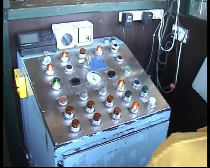
The Bush Beast was run from an operator’s panel in the station. The description of the panel and of the operating procedure on this page was provided by people who operated the ride. The layout is as they remembered it, and one or two of the lights are uncertain.
What was on the panel
Day to day the operator really only used four buttons: one brought the train into the station from the waiting brakes, one released the lap bars, one locked them, and one dispatched the train. The rest of the panel was warning and status lights driven by the ride’s computer, which also ran the compressed air system that worked the brakes and lap bars. The line gates were worked by the loader on the platform, not from the panel.
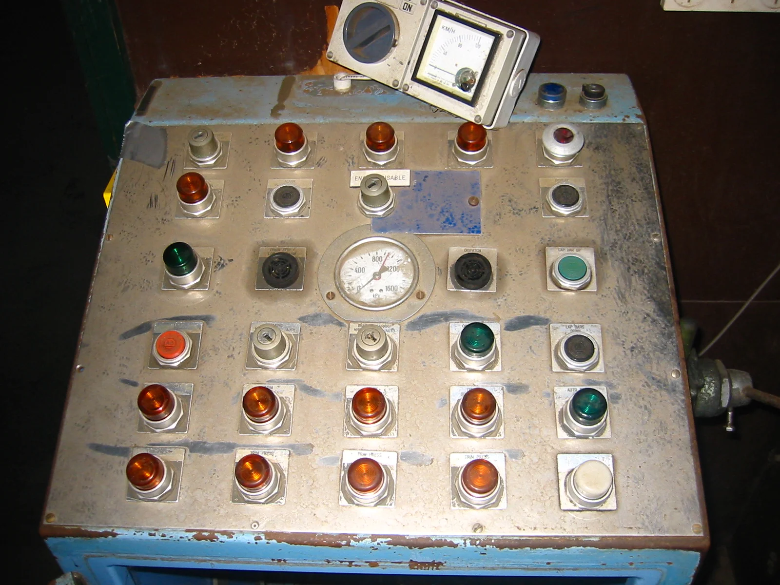
Laid out as the operators remembered it:
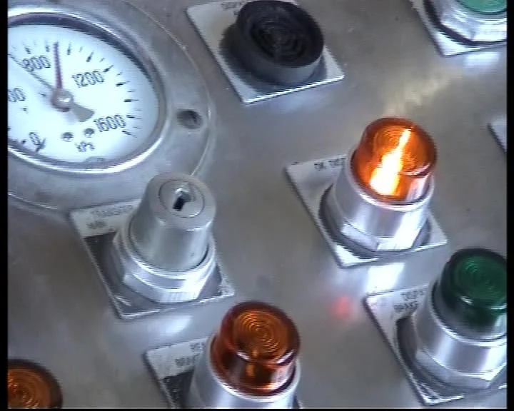
- Top left: the Control Power switch, with the Air Pressure light below it and the Alarm Silence button to the right of that light. Under the control switch was an orange light, thought to be either a “control on” indicator or an “air pressure OK” indicator.
- Top right: the red E-stop button, and a blue Ronis key switch for Control Reset.
- Top row of lights: EM Brake (second from the left), Block A (middle) and Block B (second from the right).
- Left side, third row: the Lift Start button.
- Right side: Lap Bar Up (third row) and Lap Bar Down (second row from the bottom).
- Bottom row: EM Brake Release (first on the left), Trim Brake Release next to it, Ready Brake Release (middle) and Dispatch Brake Release (second from the right).
Opening the ride in the morning
A supervisor went to the ride before opening and switched on Control Power, waited for the Air Pressure light, then pressed Alarm Silence and Lift Start. The maintenance crew left the lap bars up after their checks, so the Lap Bar Down button was tested next. The empty train was then dispatched by pressing and holding the Ready Brake Release and Dispatch Brake Release buttons until it was completely out of the station.
Once out, the train entered Block A (the Block A light came on), ran round the end of the back curve, came down the hill into Block B, and finally into the brakes at the far end of the station, where the EM Brake light and the EM Brake Release light came on. To bring it into the station the operator pressed and held EM Brake Release, then Trim Brake Release, then Ready Brake Release and finally Dispatch Brake Release, until the train was positioned correctly, and then pressed Lap Bar Up.
Running two trains
With two trains the procedure was the same, but the control system never let two trains occupy the same block: the second train could not be dispatched until the first had come off the back curve. Each train carried its sensor bars on a different side (left on one train, right on the other, plus a bar common to both) so the system knew which train was where, and a missed sensor anywhere on the track caused a safety stop. The three character diagnostic display, normally kept under a blue cover, showed which sensor had failed: 103 meant train 1, sensor 3. More on the sensors is on the Behind the Scenes page.
What survives
A former operator kept the panel’s emergency light cover, along with e-stop buttons from several other rides.
Photos 3
Got a Wonderland story or photos to share?
Join us on Facebook - share memories, photos and stories of Australia's Wonderland with thousands of other fans.
Join Wonderland History on Facebook →